Serial Buses — I2C, SPI & UART
Below the level of PCIe and USB, most chip-to-chip communication on a circuit board — a sensor talking to a microcontroller, an EEPROM storing settings, a display taking pixel data — happens over one of three much simpler serial buses: I2C, SPI, and UART. Each makes a different tradeoff between pin count, speed, and topology, and picking the right one (or reading a datasheet that assumes you know the difference) is a routine embedded-systems and hardware-interfacing task.
Core Concepts
| Term | Meaning |
|---|---|
| I2C (Inter-Integrated Circuit) | Two-wire, multi-master/multi-slave synchronous serial bus using addressing to reach a specific device. |
| SPI (Serial Peripheral Interface) | Four-wire, full-duplex synchronous serial bus using a dedicated chip-select line per device instead of addressing. |
| UART (Universal Asynchronous Receiver/Transmitter) | Asynchronous, point-to-point serial communication with no shared clock — timing is inferred from a fixed baud rate. |
| Open-drain | An output stage that can only pull a line low or let it float; a pull-up resistor is required to bring it high — I2C's SDA/SCL work this way. |
| Chip select (CS/SS) | A dedicated line an SPI controller drives to pick which single device is "listening" on the shared data lines. |
| Baud rate | The agreed-upon bit rate for UART communication; both ends must be configured to the same value since there's no shared clock line. |
| ACK/NACK | I2C's per-byte acknowledgment bit: the receiver pulls SDA low (ACK) to confirm receipt, or leaves it high (NACK). |
Mechanism
I2C — two wires, addressed, multi-master
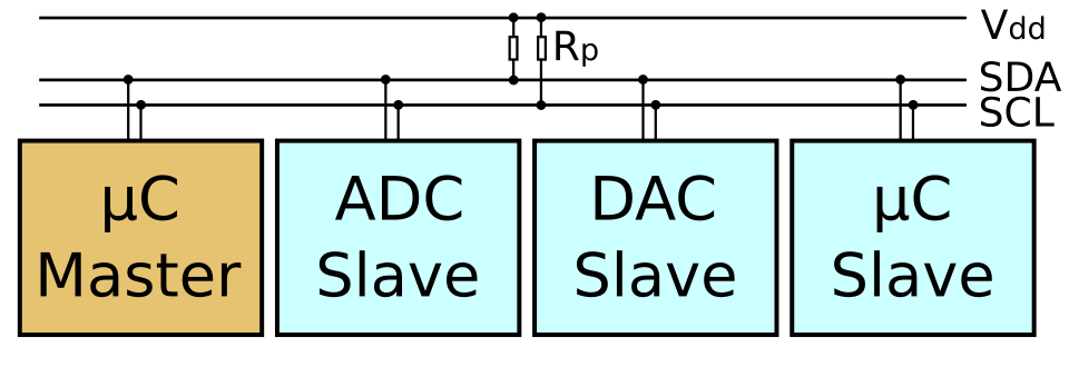
The figure uses the older master/slave labels. The current I2C specification, and this page, use controller and peripheral (or target) for the same roles.
I2C uses exactly two shared lines — SDA (data) and SCL (clock) — no matter how many devices are on the bus. Both lines are open-drain, pulled high by resistors; any device can pull either line low, which is what makes multi-master arbitration and clock stretching possible without electrical conflicts. Every transaction starts with the controller sending a 7-bit (or, less commonly, 10-bit) address to select which device should respond; that device ACKs its own address and ignores traffic addressed to anyone else.
Clock stretching: a slow slave device can hold SCL low itself to pause the controller mid-transfer until it's ready — the open-drain wiring makes this a natural extension of the same electrical mechanism used for arbitration.
SPI — four wires, full-duplex, chip-select
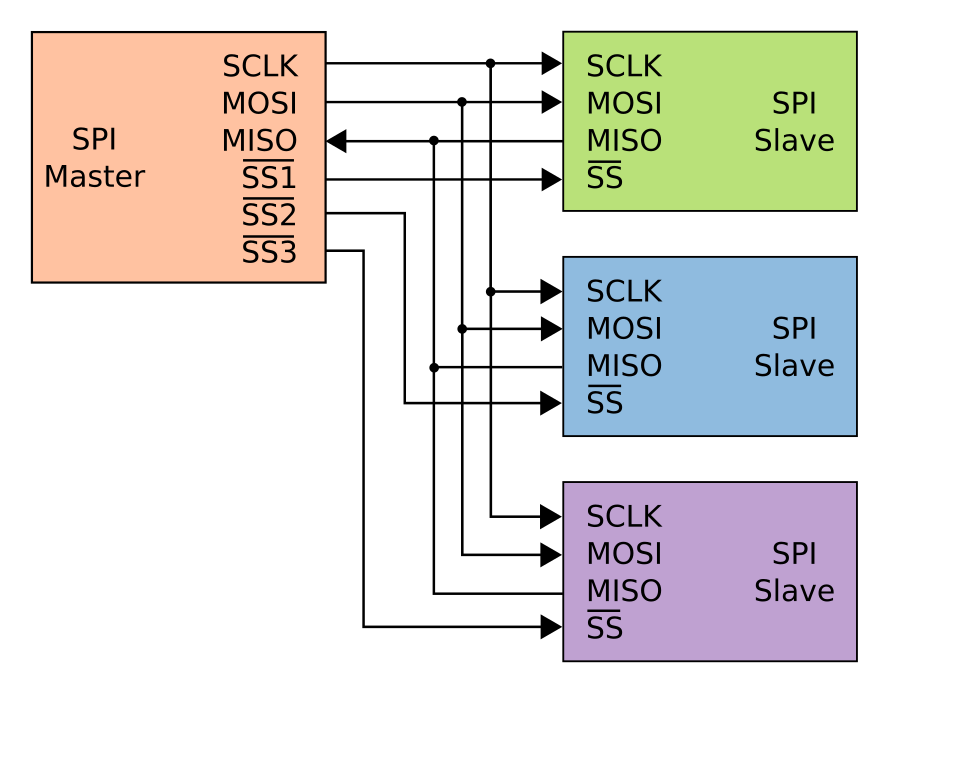
The pin count is the trade-off in one picture. I2C reaches any number of devices on two wires;
SPI needs 3 + N wires for N devices, and in exchange gets full-duplex transfers, far higher clock
rates, and no addressing or acknowledgement protocol to implement.
SPI has no addressing scheme at all. Instead, the controller wires a separate chip-select line to each device and asserts exactly one at a time — whichever device sees its CS line active is the one listening/responding. Data moves on two separate lines, MOSI (controller-out) and MISO (controller-in), driven by a shared clock (SCLK), so a full read and write can happen simultaneously (full-duplex) — something I2C's single shared data line can't do.
Unlike I2C (formally specified by NXP/Philips) or USB (formally specified by USB-IF), SPI has no single official specification. It originated as a Motorola feature on early-1980s microcontrollers, described in a Motorola application note, and became a de facto industry convention. This is why SPI implementations vary in details like clock polarity/phase modes (CPOL/CPHA — "SPI mode 0-3"), word size, and whether multiple chip-selects or daisy-chaining are supported — always check the specific device's datasheet.
UART — asynchronous, no shared clock
UART connects exactly two devices, one wire each direction (plus ground) — no shared clock line at all. Instead, both ends are configured with the same baud rate in advance, and the receiver recovers timing from start and stop bits framing each byte:
Because there's no shared clock, both sides must agree on baud rate, data bits, parity, and stop bits
out of band (a common convention is written as, e.g., "9600 8N1"). This is the classic serial port /
/dev/ttyUSB0 style interface still used for console access to routers, microcontroller debug output,
and GPS modules.
Practical Usage
A typical embedded PCB mixes all three: a UART for a debug console, I2C for a handful of low-speed sensors (temperature, accelerometer, RTC) where pin count matters more than speed, and SPI for anything needing real throughput — an SD card, a TFT display, or an external flash chip. Reading a sensor's datasheet, the "Interfaces" section will name one of these three (or occasionally both I2C and SPI as configurable options on the same chip).
Edge Cases & Pitfalls
Two devices of the same model on one I2C bus (e.g., two identical sensors) often ship with the same fixed 7-bit address, causing a collision. Many parts expose one or two address-select pins to work around this; if not, an I2C multiplexer chip is the usual fix.
I2C and SPI signal levels depend entirely on the pull-up/supply voltage each device expects (commonly 3.3 V or 5 V). Wiring a 5V device's SDA/SCL directly to a 3.3V-only microcontroller can exceed the input tolerance of the 3.3V part — use a level shifter, don't assume compatibility.
- SPI's lack of acknowledgment means the controller has no built-in way to know if a device actually received data correctly — error checking, if any, must be built into the higher-level protocol.
- UART has no flow control by default; if the receiver can't keep up, bytes are simply lost unless hardware flow control (RTS/CTS) or a higher-level protocol handles it.
- I2C's open-drain design limits both speed and bus length — long wires or many devices add capacitance, which is why speed modes specify a maximum bus capacitance alongside a clock rate.
Comparisons
| Aspect | I2C | SPI | UART |
|---|---|---|---|
| Pin count | 2 (SDA, SCL) + ground | 4+ (MOSI, MISO, SCLK, + 1 CS per device) | 2 (TX, RX) + ground |
| Clock | Shared (SCL) | Shared (SCLK) | None — fixed baud rate agreed in advance |
| Duplex | Half-duplex (one data line) | Full-duplex | Full-duplex (separate TX/RX wires) |
| Addressing | Yes — 7/10-bit device address on the bus | No — one dedicated chip-select line per device | No — point-to-point only |
| Typical speed | Up to 100 kbit/s (Standard) - 3.4 Mbit/s (High-speed) | Often tens of MHz, device-dependent (no fixed ceiling) | Typically 9.6 kbit/s - a few Mbit/s |
| Topology | Multi-master, multi-slave, one shared bus | One controller, multiple targets via separate CS lines | Strictly point-to-point (two devices) |
| Standardization | Formal spec (NXP/Philips UM10204) | De facto standard, no formal spec (Motorola-originated) | Loosely standardized (framing conventions, not electrical) |
| Typical use | Low-speed sensors, EEPROMs, RTCs on a PCB | SD cards, displays, flash chips — anything needing throughput | Debug consoles, GPS modules, simple point-to-point links |
References
- NXP Semiconductors, UM10204: I2C-bus specification and user manual — the authoritative I2C reference; defines Standard-mode (100 kbit/s), Fast-mode (400 kbit/s), Fast-mode Plus (1 Mbit/s), and High-speed mode (3.4 Mbit/s).
- Motorola / NXP, AN991: Using the Serial Peripheral Interface to Communicate Between Multiple Microcomputers — the closest thing to an "official" SPI reference document.
- The Linux Kernel documentation, Overview of Linux kernel SPI support — explicitly notes SPI's lack of a formal standard.
Books & Videos
- Ben Eater, SPI: The serial peripheral interface (YouTube) — hands-on logic-analyzer walkthrough of SPI signaling.
- Ben Eater, The RS-232 protocol (YouTube) — asynchronous serial framing (start/stop bits, baud rate) demonstrated with a breadboard UART.