The OSI and TCP/IP Models
Two competing layer models are used to describe networking: the OSI model (7 layers, designed by committee in the late 1970s/80s as a vendor-neutral standard) and the TCP/IP model (4-5 layers, which grew organically out of the actual protocols that run the Internet). OSI is what almost every textbook and certification exam teaches; TCP/IP is what the real Internet actually runs. Understanding both — and how they map onto each other — is what lets you translate between "the way this is taught" and "the way this actually works in a packet capture."
Core Concepts
| Term | Meaning |
|---|---|
| Layer | A self-contained set of responsibilities that exposes a simple interface to the layer above it, hiding how the layers below are implemented. |
| Encapsulation | Each layer wraps the data handed down from the layer above in its own header (and sometimes trailer) before passing it to the layer below. |
| PDU (Protocol Data Unit) | The name for a chunk of data at a given layer — segment (transport), packet (network), frame (data link). |
| De-encapsulation | The reverse process at the receiving end: each layer strips its own header and hands the remainder up to the layer above. |
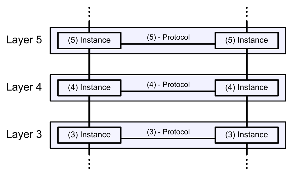
| Peer layer | The equivalent layer on the other end of a connection — conceptually, layer N on the sender "talks to" layer N on the receiver, even though the bits actually travel down and back up through every layer. |
Mechanism: Mapping the Two Models
| OSI Layer | OSI Name | TCP/IP Layer | Example protocols |
|---|---|---|---|
| 7 | Application | Application | HTTP, DNS, TLS, SMTP |
| 6 | Presentation | Application | (data formatting/encryption — folded into Application in practice) |
| 5 | Session | Application | (connection/session management — also folded into Application) |
| 4 | Transport | Transport | TCP, UDP |
| 3 | Network | Internet | IP, ICMP |
| 2 | Data Link | Link (Network Access) | Ethernet, Wi-Fi (802.11), ARP |
| 1 | Physical | Link (Network Access) | Copper, fiber, radio |
What layering means on the wire
Layers are not a filing system for concepts — they are literally nested headers. Each layer wraps the layer above it, so what leaves the network card is an onion:
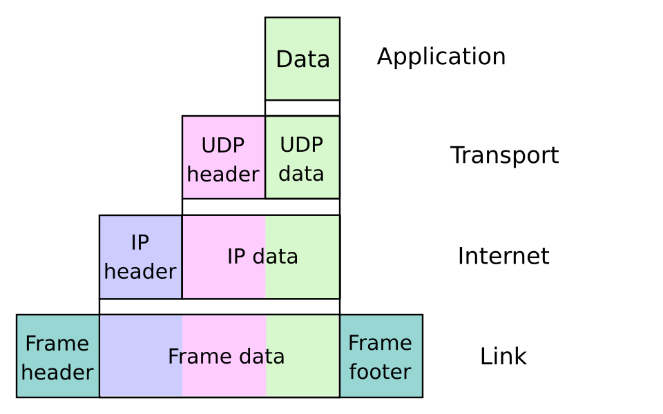
Reading that figure bottom-up is what a packet capture does, and reading it top-down explains why every layer costs you payload space — the widening bars are header overhead. It also shows why a layer can be swapped out without the others noticing: replace the link row with Wi-Fi instead of Ethernet, and nothing above it changes.
Peers talk to peers. Layer 4 on this host is in conversation with layer 4 on the other host, even though every byte physically travels down to the wire and back up:
OSI's protocols (X.25, CLNP, etc.) were designed top-down by committee before much real-world deployment experience existed, and the full stack was heavyweight to implement. TCP/IP grew bottom-up from working code on ARPANET/the early Internet — "rough consensus and running code." By the time OSI's protocols were production-ready, TCP/IP already had a critical mass of running networks and simply never got displaced. OSI's model survived as a teaching and troubleshooting tool even though its protocols mostly didn't.
Encapsulation, Step by Step
Each header carries exactly the information that layer's peer needs: the TCP header carries port numbers and sequence numbers, the IP header carries source/destination IP addresses, and the Ethernet frame carries source/destination MAC addresses. A router only needs to look as deep as the IP header to forward a packet; a switch only needs to look as deep as the Ethernet header.
Practical Usage: Seeing the Layers in a Packet Capture
Running tcpdump or Wireshark on a curl http://example.com request shows the encapsulation directly.
A one-line summary from tcpdump -i eth0 -n port 80:
14:32:01.123456 IP 192.168.1.10.54321 > 93.184.216.34.80: Flags [S], seq 123456789, win 64240, length 0
Reading this against the model:
IP 192.168.1.10.54321 > 93.184.216.34.80— the Internet layer (IP addresses) and Transport layer (port54321→ port80) information, both visible becausetcpdumpdecodes headers for you.Flags [S]— a TCP SYN flag, part of the three-way handshake.- The Ethernet header (source/destination MAC) is layer 2 and is normally hidden by
tcpdump's default output, but is present in every frame — add-eto see it.
Edge Cases & Pitfalls
Real protocols don't always respect the model cleanly. TLS is often drawn "between" transport and application, but functions more like a session/presentation-layer concern (OSI layers 5-6) wrapped around application data. QUIC (used by HTTP/3) implements transport-layer reliability and built-in encryption in a single UDP-based protocol, blurring the transport/security boundary further. Treat the model as a mental map, not a strict specification every protocol obeys.
- A common exam mistake: assuming a switch operates at layer 3. Switches forward on MAC addresses (layer 2); routers forward on IP addresses (layer 3). See Data Link Layer and Network Layer & Routing.
- The "TCP/IP model" is sometimes drawn with 4 layers and sometimes with 5 (splitting Link into Physical + Data Link) — there's no single canonical source, unlike OSI's fixed 7 layers from ISO/IEC 7498-1.
Comparisons
| Aspect | OSI Model | TCP/IP Model |
|---|---|---|
| Layers | 7 | 4 (sometimes drawn as 5) |
| Origin | ISO committee standard (top-down design) | Grew from working ARPANET/Internet protocols (bottom-up) |
| Real-world protocol stack | Rarely implemented in full | This is the real Internet |
| Primary use today | Teaching, troubleshooting vocabulary ("layer 2 issue", "layer 7 firewall") | Actual specification of how the Internet works |
References
- ISO/IEC 7498-1, Information technology — Open Systems Interconnection — Basic Reference Model — the formal OSI model standard.
- IETF, RFC 1122 — Requirements for Internet Hosts — Communication Layers, one of the closest things to an official description of the Internet/TCP-IP layering.
- Kurose & Ross, Computer Networking: A Top-Down Approach — structures its entire narrative around the layered model, starting from the application layer down.
Books & Videos
- Kurose & Ross, Computer Networking: A Top-Down Approach — the standard modern textbook; Chapter 1 covers protocol layering and encapsulation in depth.
- Ilya Grigorik, High Performance Browser Networking (free online) — Part I covers the transport-layer building blocks referenced throughout this section.